Week 7: RoboSumo Prep

11th of March 2020

Disclaimer!

Due to the COVID-19 Pandemic, we are no longer able to continue with this project. I have thoroughly enjoyed working on this project with my team mates Nathan and Nader. We had our struggles together with our robot malfunctioning, the chassis not being up to par, and replacements of parts but had many success with codes working as they should, the parts working separately and together, and also learning a lot during this journey. We had strong motivation to improve our robot as much as we could and learning from our mistakes but unfortunately that’s not possible at the moment.

Intro

This week, my team and I decided to start fresh. We decided to come up with a brand new design and building it using laser cutting. This decision was made as we thought that the dimensions would be more exact which would decrease the risk of exceeding the measurement limit.

Nathan is responsible for the making of the chassis material now and Nader and I are working on reprogramming our robot.

Design

I also decided to come up with a design which was approved by my team. The idea I thought would work well was for our robot to have a low centre of gravity with a wide and steady base. This so that our robot will have no way of being tipped over whilst also being much faster.

not to scale rough sketch of new design

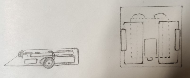
Nathan is planning to properly sketch the design in autocad and then later convert it to a 3D printable file. This will be 3D printed as the material is lighter which would be beneficial to our weight limit. We also didn’t want the robot to be too light so we are also thinking of adding metal fastenings to add weight to our robot which would aid it in pushing out other robots from the table.

IR Sensor

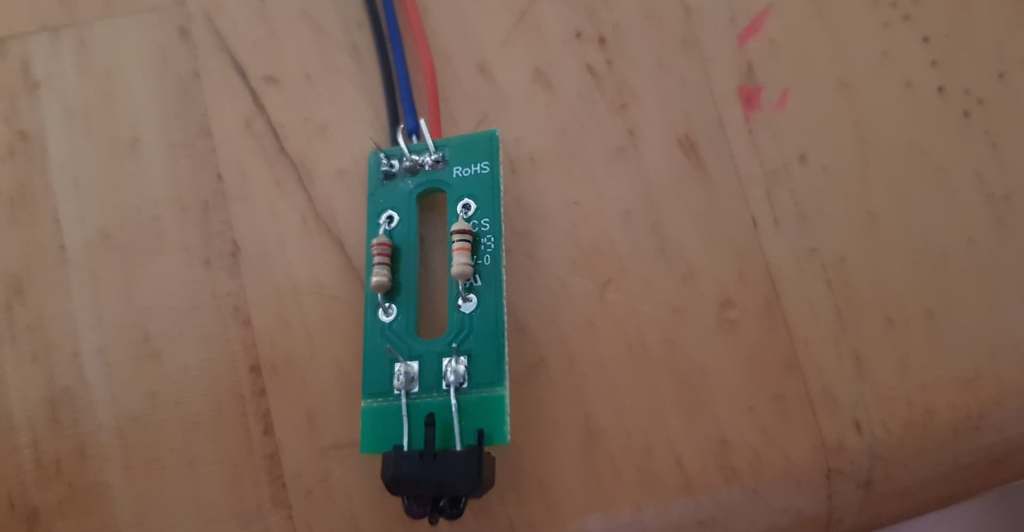
Below is a completed IR sensor. This will be used to prevent our robot from falling off the RoboSumo table where our robots will be placed to battle one another. The table is black and circular with a white outer rim. When the sensor detects the white rim, the robot will reverse.

While Nader and I worked on planning, Nathan decided to take a look at the IR Sensor, assemble, and solder it. The components given are a TCRT5000 IR reflective sensor, a 10kΩ and 220Ω resistor, and 1 DIT_RS_CS5 PCB.

A guide on how to construct the sensor can be found on https://robosumo.wordpress.com/2019/10/09/assembly-instructions-for-tcrt5000-printed-circuit-board/ . As we would have used two of these sensors, I would have to find a way to add them to the design without exceeding the measurement limit.

colour sensor

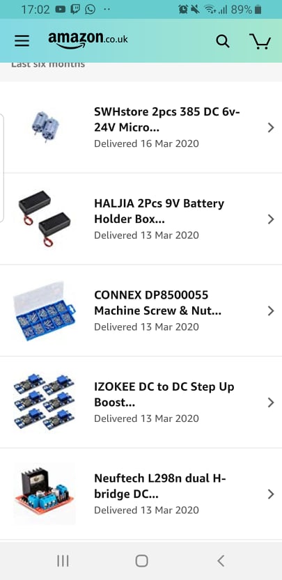
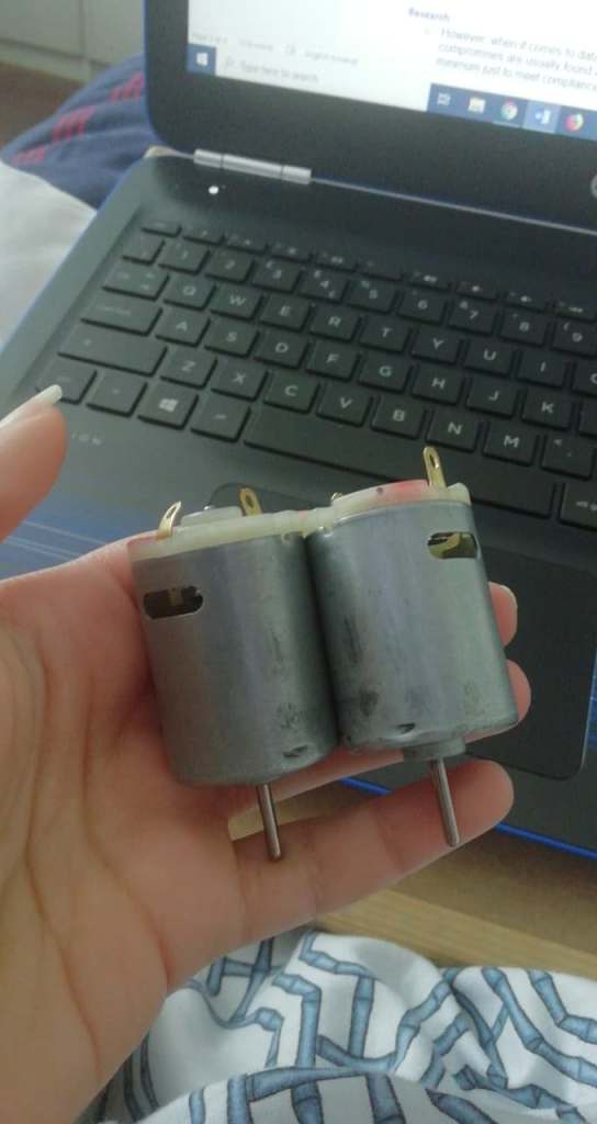
Here are some of the components Nader has purchased for our robot.

new parts ordered
new motors

Roles during the Project

  • Nathan: Program, CAD, hardware
  • Nader: Hardware, program
  • Andrea: Design, program, organising

Week 6: Tip the Can Week 2

4th of March 2020

This week is second of the Tip the Can challenge. This week is for anyone who didn’t get an opportunity to tip the can in week 1.

We once again tried to change our code and chassis to resolve the problem of what happened in week 1 but once again, none of that worked. By the end of the challenge, we decided to shift our attention to prepping our robot for the Robosumo tournament for next week.

Final circuit diagram by Nathan

Code for Tip the Can Challenge week 2

int trigPin = 9; //Defining trigpin
int echoPin = 10; //Defining echopin
long duration, cm, inches;

void setup()
{
 Serial.begin (9600);
 pinMode(trigPin, OUTPUT); //triggerpin on rangefinder as an output
 pinMode(echoPin, INPUT); //Echopin on rangefinder as an input
 pinMode(3, OUTPUT); //motors
 pinMode(4, OUTPUT); //motors
 pinMode(6, OUTPUT); //motors
 pinMode(7, OUTPUT); //motors
 pinMode(5, INPUT); //Switch input
}

void loop()
{
long duration, distance; //defining variables
//pulse from HC-SR04
digitalWrite(trigPin, LOW); //Calibrate Trigpin
delayMicroseconds(2);
digitalWrite(trigPin, HIGH); //send out signal from trigpin
delayMicroseconds(10);
duration = pulseIn(echoPin, HIGH); //Recieve signal in echopin
distance = duration*0.034/2; //defines distance to object in cm
Serial.print(distance);
Serial.println("cm");
//check echo pulse
if (distance <60 ) //If the distance is less than 60cm
{

 digitalWrite (4,LOW); //move towards object
 digitalWrite (3,HIGH);
 digitalWrite (7,HIGH);
 digitalWrite (6,LOW);

}
else {
digitalWrite (4,LOW); //rotate until distance is less than 60cm
digitalWrite (3,LOW);
digitalWrite (6,LOW );
digitalWrite (7,LOW);
}
int x; //defining x
x = digitalRead(5); //read input
Serial.print("The Switch is now:");
Serial.println(x);
//If switch is pressed
if (x == 1){


 digitalWrite (3,HIGH); //reverse for 5 seconds
 digitalWrite (4,LOW);
 digitalWrite (6,HIGH);
 digitalWrite (7,LOW);
delay(5000);

 digitalWrite (3,LOW); //stop for 10 seconds
 digitalWrite (4,LOW);
 digitalWrite (6,LOW);
 digitalWrite (7,LOW);
delay(10000);
}
}
Naders design

Week 5 : Tip the Can Week 1

26th of February 2020

This week is the Tip the Can Challenge week 1. This challenge required us to programme our robot to find the robotic can, touch it for 1 second, reverse, and stop, while all being timed, using all the parts we had previously worked on. If the can lit a green light, then you have successfully completed the challenge. If the light turns red, then your time is recorded as non compliant.

Tip the Can Ranking Ruled by Ted Burke

Unfortunately, my team did not get to complete the challenge this week as our robot was not functioning properly. Our robot had difficulty locating any object that was placed in front of it and we also had issues with the chassis as our robot kept tipping forward.

We tried to correct the code and change up the chassis but none of that worked. Hopefully next week will work out better.

Tip the Can code week 1

//GROUP 90 TIP THE CAN

int trigPin = 9; //Defining trig pin
int echoPin = 10; //Defining echo pin
long duration, cm, inches;

void setup(){
 Serial.begin (9600);
 pinMode(trigPin, OUTPUT); //Trigpin is an output
 pinMode(echoPin, INPUT); //Echopin is an input
 pinMode(3, OUTPUT); //motors
 pinMode(4, OUTPUT); //motors
 pinMode(6, OUTPUT); //motors
 pinMode(7, OUTPUT); //motors
 pinMode(5, INPUT); //Switch input
}

void loop() {
int x; //switch setup
x = digitalRead(5);
Serial.print("The Switch is now:");
Serial.println(x);

long duration, distance; //defining variables
//pulse from HC-SR04
digitalWrite(trigPin, HIGH); //pulse for 20 micro seconds
delayMicroseconds(20);
digitalWrite(trigPin, LOW);
duration = pulseIn(echoPin, HIGH);
distance = (duration/2)*0.034;
Serial.print(distance);
Serial.println("cm");
//check echo pulse if less than 20 cm
if (distance <20) {

//(digitalRead(echoPin) == 1)
 digitalWrite(3, LOW); //MOTORS FORWARD
 digitalWrite(4, HIGH);
 digitalWrite(6, LOW);
 digitalWrite(7, HIGH);

 if (x == 1){
 digitalWrite(3, HIGH); //REVERSE
 digitalWrite(4, LOW);
 digitalWrite(6, HIGH);
 digitalWrite(7, LOW);
 delay(2000);

 digitalWrite(3, LOW); //STOP
 digitalWrite(4, LOW);
 digitalWrite(6, LOW);
 digitalWrite(7, LOW);
 delay(60000);

}

}
else {
 digitalWrite(3, LOW); //SCAN MODE, ROBOT RIGHT
 digitalWrite(4, HIGH);
 digitalWrite(6, HIGH);
 digitalWrite(7, LOW);
 delay(250);

 digitalWrite(3, LOW);
 digitalWrite(4, HIGH);
 digitalWrite(6, HIGH);
 digitalWrite(7, LOW);
 delay(250);

 digitalWrite(3, LOW);
 digitalWrite(4, HIGH);
 digitalWrite(6, HIGH);
 digitalWrite(7, LOW);
 delay(250); 
}
}
part of Andrea’s Design
Nathan’s Design

Week 4 : Rangefinder

19th of February 2020

This week we’re working on the rangefinders. The rangefinder acts like the eyes of the robot, measuring distance. It functions by sending out sound signals from the transmitter and receives these sounds after it gets deflected back by the object. These signals travel at the speed of sound.

One of the part controlled by the trigger pin sends out a pulse. That pulse is reflected off a surface in front of it, and that pulse is read by the part linked to the echo pin.

Drawing of Rangefinder

Code for Rangefinder

//Nathan Martin
//rangefinder code

//Change Pin names to identify them easier
int trigPin = 9;
int echoPin = 10;
long duration, cm, inches;

void setup()
{
Serial.begin (9600);
pinMode(trigPin, OUTPUT); //Rangefinder Pins
pinMode(echoPin, INPUT);
pinMode(3, OUTPUT); //Motor Pins
pinMode(4, OUTPUT);
pinMode(6, OUTPUT);
pinMode(7, OUTPUT);
}

void loop()
{
long duration, distance; //defining variables

//pulse from HC-SR04
digitalWrite(trigPin, HIGH); //pulse for 20 micro seconds
delayMicroseconds(20);
digitalWrite(trigPin, LOW);

duration = pulseIn(echoPin, HIGH);
distance = (duration/2)*0.034;

Serial.print(distance);
Serial.println(“cm”);

//check echo pulse
if (distance <20)
//(digitalRead(echoPin) == 1)
{

digitalWrite (3,LOW); //Set Both Motors to move “Clockwise” “Backwards”
digitalWrite (4,HIGH);
digitalWrite (6,LOW);
digitalWrite (7,HIGH);
delay(1000);

}
else
digitalWrite (3,HIGH); //Set Both Motors to move “Clockwise” “Backwards”
digitalWrite (4,LOW);
digitalWrite (6,HIGH );
digitalWrite (7,LOW);
{

}

}

Circuit diagram of how the rangefinder is connected to the Arduino by Nader Maloudi

Week 3: The Switch

12th of February 2020

This week, we worked on the switch. For our robot, when the switch is pressed, the Arduino would receive that signal which would then rotate the motors in reverse making the robot go backwards. This is so that the robot would know that it has touched an object and not continue to move forward.

Drawing of the switch

Code for the switch

/Programming the Switch
//Written By Andrea Lafford

void setup()
{
// put your setup code here, to run once:
pinMode(3, OUTPUT); // Motor Pins
pinMode(4, OUTPUT);
pinMode(6, OUTPUT);
pinMode(7, OUTPUT);

pinMode(5, INPUT); //Switch Pin
}

void loop()
{
int x;
x = digitalRead(5);

if (x == 1)
{
//Left motor forward for 5 sec
digitalWrite (3,HIGH); //Set Both Motors to move "CounterClockwise" "Forward"
digitalWrite (4,LOW);
digitalWrite (6,HIGH);
digitalWrite (7,LOW);

}
else
{
digitalWrite (3,LOW); //Set Both Motors to move "Clockwise" "Backwards"
digitalWrite (4,HIGH);
digitalWrite (6,LOW);
digitalWrite (7,HIGH);

}
}

Week Two: Motors

5th of Febuary 2020

This week, we programmed our motors. An SN754410NE driver was used to increase the current going through the motors. without it, the motors speed would be decreased. Below is the Pin Configuration and Functions for the driver chip. Here is where you can find the data sheet: http://www.ti.com/lit/ds/symlink/sn754410.pdf

Here is how the motors were connected to the driver chip on the circuit.

motor dimensions

The motors were programmed to spin in specific directions for a certain amount of time.

Code for Motors

//Andrea Lafford and Nader Maloudi
//Code for Motor Directions


void setup() {
// put your setup code here, to run once:

Serial.begin(9600);

//Set motors to chosen pins on the Arduino chip

pinMode(4, OUTPUT);
pinMode(3, OUTPUT);
pinMode(7, OUTPUT);
pinMode(6, OUTPUT);

}

void loop() {

digitalWrite (3,HIGH); //Set Both Motors to move "CounterClockwise" "Forward"
digitalWrite (4,LOW);
digitalWrite (6,HIGH);
digitalWrite (7,LOW);

delay(2000); // 2 second duration of action

digitalWrite (3,LOW); //Set Both Motors to STOP
digitalWrite (4,LOW);
digitalWrite (6,LOW);
digitalWrite (7,LOW);

delay(2000);

digitalWrite (3,LOW); //Set Both Motors to move "Clockwise" "Backwards"
digitalWrite (4,HIGH);
digitalWrite (6,LOW);
digitalWrite (7,HIGH);

delay(2000);

digitalWrite (3,LOW); //Set Both Motors to STOP
digitalWrite (4,LOW);
digitalWrite (6,LOW);
digitalWrite (7,LOW);

delay(2000);

digitalWrite (3,HIGH); //Set right motor go "clockwise" and left motor to go "counterclockwise"
digitalWrite (4,LOW);
digitalWrite (6,LOW);
digitalWrite (7,HIGH);

delay(2000);

digitalWrite (3,LOW); //Set Both Motors to STOP
digitalWrite (4,LOW);
digitalWrite (6,LOW);
digitalWrite (7,LOW);

delay(2000);

digitalWrite (3,LOW); //Set right motor go "counterclockwise" and left motor to go "clockwise"
digitalWrite (4,HIGH);
digitalWrite (6,HIGH);
digitalWrite (7,LOW);

delay(2000);

digitalWrite (3,LOW); //Set Both Motors to STOP
digitalWrite (4,LOW);
digitalWrite (6,LOW);
digitalWrite (7,LOW);

delay(5000); // 5 second duration of action

}
circuit diagram

To test if the motors are functioning, connect the input leads into ground.


Week 1 : LED Flash Challenge

29th of January 2020

The first task we were given was to light an LED on and off using the Arduino chip. We did this using the code below. The reasoning behind this task was to familiarise ourselves with how the Arduino functions and to set up circuits properly.

Code for LED Flash Challenge par 1

//LED Flah challenche part 1
//Andrea Lafford
//29th Jnuary 2020


// The setup routine runs once when the power is switched on.
void setup()

{
  // Digital output for LED 1 on pin D2
  pinMode(2, OUTPUT);
}
 

// The loop routine runs over and over until the power is switch off.
void loop() 
{
  
digitalWrite(2, HIGH);  // LED on
delay(1000);           // 1000ms delay

digitalWrite(2, LOW);  // LED off
delay(1000);           // 1000ms delay

}

//This Action is repeated indefinitely until turned off

Video demonstrating LED turning on and off


Image showing circuit

*Our second task was to convert out team number into binary code. Using the binary code, we had to programme the LEDs to display said code by assigning ones and zeros to each LED. LED 1 would turn on if a one was to be displayed, and LED 2 would turn on if a zero was to be displayed. To check if our binary was correct, we used the website https://tedburke.github.io/LEDFlashChallenge/video.html. The following was displayed when the code was correct. -+

Code for LED Flash Challenge part 2

//Andrea Lafford
//LED Flash Challenge part 2
//29th January 2020


// The setup routine runs once when the power is switched on.
void setup()

{
// Digital output for LED 1 on pin D2
pinMode(2, OUTPUT);
// Digital output for LED 2 on pin D5
pinMode(5, OUTPUT);
}

// The loop routine runs over and over until the power is switch off.
void loop()

{
digitalWrite(2, LOW); // LED off
digitalWrite(5, HIGH); // LED on
delay(5000); // 5000ms delay

digitalWrite(2, HIGH); // LED on
digitalWrite(5, LOW); // LED off
delay(500); // 500ms delay

digitalWrite(2, LOW); // LED off
digitalWrite(5, HIGH); // LED on
delay(500); // 500ms delay

digitalWrite(2, HIGH); // LED on
digitalWrite(5, LOW); // LED off
delay(500); // 500ms delay

digitalWrite(2, LOW); // LED off
digitalWrite(5, HIGH); // LED on
delay(500); // 500ms delay

digitalWrite(2, HIGH); // LED on
digitalWrite(5, LOW); // LED off
delay(500); // 500ms delay

digitalWrite(2, HIGH); // LED on
digitalWrite(5, LOW); // LED off
delay(500); // 500ms delay

digitalWrite(2, LOW); // LED off
digitalWrite(5, HIGH); // LED on
delay(500); // 500ms delay

digitalWrite(2, HIGH); // LED on
digitalWrite(5, LOW); // LED off
delay(500); // 500ms delay

digitalWrite(2, LOW); // LED off
digitalWrite(5, HIGH); // LED on
delay(500); // 500ms delay

digitalWrite(2, LOW); // LED off
digitalWrite(5, HIGH); // LED on
delay(500); // 500ms delay

digitalWrite(2, HIGH); // LED on
digitalWrite(5, LOW); // LED off
delay(500); // 500ms delay

digitalWrite(2, HIGH); // LED on
digitalWrite(5, LOW); // LED off
delay(500); // 500ms delay

digitalWrite(2, LOW); // LED off
digitalWrite(5, HIGH); // LED on
delay(500); // 500ms delay

digitalWrite(2, HIGH); // LED on
digitalWrite(5, LOW); // LED off
delay(500); // 500ms delay

digitalWrite(2, LOW); // LED off
digitalWrite(5, HIGH); // LED on
delay(500); // 500ms delay

digitalWrite(2, LOW); // LED off
digitalWrite(5, HIGH); // LED on
delay(500); // 500ms delay

digitalWrite(2, HIGH); // LED on
digitalWrite(5, LOW); // LED off
delay(500); // 500ms delay

digitalWrite(2, LOW); // LED off
digitalWrite(5, HIGH); // LED on
delay(500); // 500ms delay

digitalWrite(2, HIGH); // LED on
digitalWrite(5, LOW); // LED off
delay(500); // 500ms delay

digitalWrite(2, LOW); // LED off
digitalWrite(5, HIGH); // LED on
delay(5000); // 5000ms delay

}

Video demonstrating LED Flash Challenge

Image of Circuit

About the Project

What is this project and why are we doing it?

If you’ve ever watched Robot Wars then you’re already ahead in understanding what this project intales!

My name is Andrea and I am currently an Engineering student in TU Dublin (formerly known as DIT). My team, Team 90, consists of Nathan, Nader, and myself.

This Design Project was given to us in our first year of the course to get a basic understanding of how to programme, build, and design. Yes, a working Robot is what my team and I had strived to build from start to finish, but that wasn’t the reason this Project was given to us in the first place.

From my understanding, this helped bring all aspects of Engineering into one, and shows how we all need to understand how each area functions and come together to create something.

So now, to talk about the actual project itself.

Firstly, we are put into teams. The project is spilt into two parts. The first 4-5 weeks are working towards “Tip the Can” and the last few weeks are to refine and improve your robot for the Ultimate RoboSumo Tournament (more in detail in later blog posts). We are then marked and graded on our robots performance against all other teams in the course.

Hopefully this Blog allows you to see the inner workings of our Robot in depth and maybe you too can gain the confidence to build one.

Design a site like this with WordPress.com
Get started